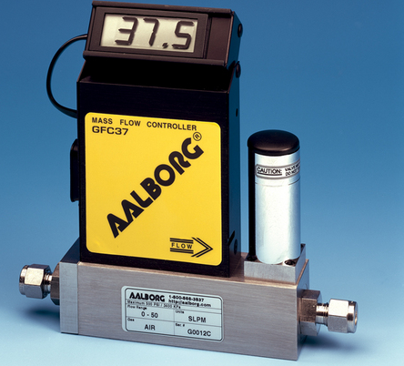
GFC Mass Flow Controller
Design Features
- ± 1% FS accuracy is standard
- rigid metallic construction
- available flow ranges starting from 0 to 10 sccm up to 0 to 1000 slpm
- maximum pressure of 1000 psig (70 bars)
- leak integrity 1 x 10⁻⁹ sccs of helium
- NIST traceable certification
- built-in tiltable LCD readout (some models)
- local or remote setpoint control
- 0-5 Vdc and 4-20 mA signals
- circuit protection
- totalizer option
Description
GFC mass flow controller
Model GFC thermal Mass Flow Controllers are designed to indicate and control set flow rates of gases.
The GFC combines the characteristics, and accuracy of conventional mass flow devices into a unique compact design at low costs previously unattainable. Each of these controllers incorporates an advanced straight tube sensor in conjunction with flow passage elements constructed of aluminum and brass for non-corrosive gases or 316 stainless steel for corrosive applications. Zero and span adjustments are accessible from the outside of transmitters.
Principles of Operation
Metered gases are divided into two laminar flow paths, one through the primary flow conduit, and the other through a capillary sensor tube. Both flow conduits are designed to ensure laminar flows and therefore the ratio of their flow rates is constant.
Two precision temperature sensing windings on the sensor tube are heated, and when flow takes place, gas carries heat from the upstream to the downstream windings. The resultant temperature differential is proportional to the change in resistance of the sensor windings.
A Wheatstone bridge design is used to monitor the temperature dependent resistance gradient on the sensor windings which is linearly proportional to the instantaneous rate of flow.
Output signals of 0 to 5Vdc and 4 to 20mA are generated indicating mass molecular based flow rates of the metered gas.
The combined gas streams flow through a proportionating electromagnetic valve with an appropriately selected orifice. The closed loop control circuit continuously monitors the mass flow output and maintains it at the set flow rate.
Flow rates are unaffected by temperature and pressure variations within stated limitations.
General Description
Compact, self contained GFC mass flow controllers are designed to indicate and control flow rates of gases. The rugged design coupled with instrumentation grade accuracy provides versatile and economical means of flow control. Aluminum or stainless steel models with readout options of either engineering units (standard) or 0 to 100 percent displays are available.
The built-in electromagnetic valve allows the flow to be set to any desired flow rate within the range of the particular model. The valve is normally closed as a safety feature to ensure that gas flow is shut off in case of a power outage. Setpoints are controlled either locally or remotely.
The LCD readout built into the top of the transducer is tiltable over 90 degrees to provide optimal reading comfort. It is connected to the transducer by a standard modular plug, and is readily removable for remote reading installations. Transducers without LCD readout are offered for OEM applications.
GFC mass flow controllers are available with flow ranges from 10 sccm to 1000 sL/min N2. Gases are connected by means of 1/4”, 3/8”, or optional 1/8” compression fittings and 3/4” FNPT fittings. Optional fittings are available. These controllers may be used as benchtop units or mounted by means of screws in the base.
Transducer power supply ports are fuse and polarity protected.
Leak Integrity
1 x 10⁻⁹ smL/sec of helium maximium to the outside environment.

