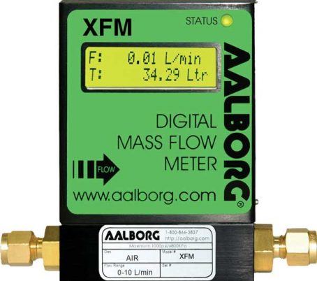
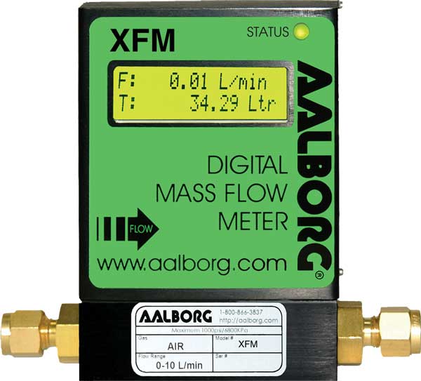
XFM Digital Mass Flowmeter
Design Features
- Supports up to 23 Engineering Units (including User Defined).
- Stores calibration data for up to 10 gases.
- Programmable Totalizer indicates total gas quantity.
- High and low gas flow Alarm limits with preset delay interval.
- Two sets of user-programmable electromechanical SPDT relays with latch option.
- User-selectable analog 0-5 Vdc or 4-20mA outputs.
- Internal Conversion factors for up to 32 gases.
- Digital Interface (RS-232 / RS-485, Profibus DP available).
- Multi-Drop Capability of up to 256 units (RS-485 option).
- Optional Profibus DP interface with I&M functionality.
- Automatic sensor zero offset adjustment (via digital interface or local push button).
- Self-Diagnostic Tests.
- Local 2 x 16 characters LCD display* with adjustable back light (optional).
Description
XFM digital mass flow meter
The flow rate can be displayed in 23 different volumetric flow or mass flow engineering units including user specific. Flow meters can be programmed remotely via RS-232/RS-485 or optional Profibus DP interface.
XFM flow meters support various functions including:
programmable flow totalizer, high and low flow alarm, automatic zero adjustment, 2 relay outputs, jumper selectable 0-5 Vdc or 4-20 mA analog outputs, status LED diagnostic, capable to store calibration for up to 10 different gases, internal or user-specific K-factors. Optional local 2 x 16 characters LCD display* with adjustable back light provides Flow, Total and diagnostic reading simultaneously.
Principle of Operation
The stream of gas entering the Mass Flow transducer is split by shunting a small portion of the flow through a capillary stainless steel sensor tube. The remainder of the gas flows through the primary flow conduit. The geometry of the primary conduit and the sensor tube are designed to ensure laminar flow in each branch. According to principles of fluid dynamics, the flow rates of a gas in the two laminar flow conduits are proportional to one another. Therefore, the flow rates measured in the sensor tube are directly proportional to the total flow through the transducer. In order to sense the flow in the sensor tube, heat flux is introduced at two sections of the sensor tube by means of precision-wound heater sensor coils. Heat is transferred through the thin wall of the sensor tube to the gas flowing inside. As gas flow takes place, heat is carried by the gas stream from the upstream coil to the downstream coil windings.
The resultant temperature dependent resistance differential is detected by the electronic control circuit. The measured temperature gradient at the sensor windings is linearly proportional to the instantaneous rate of flow taking place. An output signal is generated that is a function of the amount of heat carried by the gases to indicate mass molecular based flow rates. Additionally, the XFM model Mass Flow Meter incorporates a Precision Analog Microcontroller (ARM7TDMI® MCU) and non-volatile memory that stores all hardware specific variables and up to 10 different calibration tables.
Interface
The digital RS485 or RS-232 interface (optional Profibus DP interface is available) provides access to applicable internal data including: flow, CPU temperature, auto zero, totalizer and alarms settings, gas table, conversion factors and engineering units selection, dynamic response compensation and linearization table adjustment. The analog interface provides 0 to 5Vdc or 4 to 20 mA (jumper selectable) outputs for flow reading.
Auto Zero
The XFM supports automatic sensor zero offset adjustment which can be activated locally via the maintenance push button or remotely via digital interface. The auto zero feature necessitates a condition of absolutely no flow through the meter during the adjustment process. Provisions are made to either start, read, or save the current auto zero value via digital commands.
Totalizer
The total volume of the gas is calculated by integratingthe actual gas flow rate as a function of time.
The digital interface commands are provided to:
- Set the totalizer to ZERO.
- Start the totalizer at a preset flow.
- Assign action at a preset total volume.
- Start/stop totalizing the flow.
- Read totalizer.
Totalizer conditions become true when the totalizer reading and the “Stop at Total” volumes are equal. In addition, the provision is made to automatically disable Totalizer during sensor warm up period.
Flow Alarm
High and Low gas flow ALARM limits can be preprogrammed via digital interface. ALARM conditions become true when the current flow reading is equal or higher/lower than corresponding values of high and low alarm levels. Alarm action can be assigned with preset delay interval (0-3600 seconds) to activate the contact closer (separate for High and Low alarm). Latch Mode control feature allows each relay to be latched on or follow the corresponding alarm status.
Multi-Gas Calibration
The XFM is capable of storing primary calibration data for up to 10 gases. This feature allows the same XFM to be calibrated for multiple gases while maintaining the rated accuracy on each.
Conversion Factors
Conversion factors for up to 32 gases are stored in the XFM. In addition, provision is made for a user-defined conversion factor. Conversion factors may be applied to any of the ten gas calibrations via digital interface commands.
Contact Closure
Two sets of electromechanical SPDT relay outputs are provided to actuate user-supplied equipment.
These are programmable via digital interface such that the relays can be made to switch when a specified event occurs (e.g. when a low or high flow alarm limit is exceeded or when the totalizer reaches a specified value) or may be directly controlled by user.
Leak Integrity
1 x 10⁻⁹ smL/sec of Helium maximum to the outside environment.