TIO Totalizer Input/output Flow Monitor/Controller
Design Features
- Displays instantaneous, total and accumulated flow rates.
- Built-in Flow Linearizer (10 point linearization of the flow curve).
- Up to 47 different volumetric and mass flow engineering units.
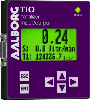
- Large 13mm (0.51″) digits for flow rate and 5.5mm (0.21″) for Total.
- Digital RS-232 or RS-485 interface (multi-drop capability of up to 64 devices.)
- Compact design for unit mount, panel mount, wall mount or field mount applications.
- User-programmable, optically-isolated pulse output.
- Two programmable, optically-isolated, digital outputs.
- Flow controllers, set point command control via local LCD or digital interface.
- Programmable set point table with ramping up/down capability up to 16 steps.
- Free Configuration and Monitoring Utility software.
Description
TIO Totalizer Input/Output Flow Monitor/Controller
Application
For flow meters and controllers with analog 0-5 (5-10) (0-10)Vdc, 4-20mA input output interface, where flow indications / control and totalizers or alarm functions are required. Also when re-transmission of the flow rate and/or totalizer functions via optically-isolated pulse output or serial communication is desired. Local or programmable set point control for flow controllers (no host PC presence required). Activation of user-supplied equipment via programmable optically-isolated digital outputs when flow alarms or totalizers events are active.
Display
The graphical LCD display has large 13mm (0.51″) digits for flow rate and 5.5mm (0.21″) for total and can be set by user to simultaneously show different combination of the flow parameters: flow rate, totalizers, flow alarms, and diagnostic events. All configuration parameter settings are easily accessed via a simple user-interface menu driven by a 6 button keypad which can be password-protected.
Signal Input and Signal Output
- 0-5 Vdc (Input/Output)
- 5-10 Vdc (Output only)
- 0-10 Vdc (Input/Output)
- 4-20 mA (Input/Output)
For flow meters and / or flow controllers, TIO provides jumpers selectable for 0-5 Vdc or 4-20 mA analog set point control signals. The flow rate set point can be adjusted locally via keypad, remotely via host PC using digital communication interface, or programmed in advance using built-in 16 steps batch table with ramping up/down support.
Programmable Pulse Output
The programmable flow pulse output is operating independently from totalizers and based on configuration settings can provide pulse frequency proportional to instantaneous fluid flow rate.
The LCD/keypad and digital communication interface commands are provided to:
- Enable/Disable Pulse Output
- Configure Pulse Output start flow rate (in % of full scale)
- Configure the Unit/Pulse value (in current volumetric or mass flow units)
- Configure Pulse Active On Time (10 – 6550 ms)
Programmable Totalizers
TIO provides two independent programmable flow totalizers. Both totalizers are updated every 100 ms and can be set to activate different events. Main totalizer accumulated total is backed-up in EEPROM memory every second.
The LCD/keypad and digital communication interface commands are provided to:
- Enable/Disable totalizing the flow
- Start the totalizer at a preset flow rate (in % of full scale)
- Assign action at a preset total volume (Event Volume)
- Configure power on delay (in seconds)
- Configure Auto Reset at preset volume
- Configure Auto Reset delay (in seconds)
- Reset the totalizer to ZERO
Programmable Alarms
TIO provides the user with a flexible alarm/warning system that monitors the fluid flow for conditions that fall outside configurable limits as well as visual feedback for the user via the LCD or via an optically-isolated output. The flow alarm has several attributes which can be configured by the user via LCD/Keypad or digital communication interface:
- Enable/Disable flow alarm
- Low flow alarm settings (in % of full scale)
- High flow alarm settings (in % of full scale)
- Flow alarm action delay
- Flow alarm action latch mode
Digital Communication
All process data and settings can be read and modified manually via local LCD Keypad or through the digital RS-232 or RS-485 communication interface. Proprietary ASCII software interface command set and free Communication Utility software are provided.